Common line laser cutting, a precise sheet metal processing technology. The technology could solve several drawbacks of traditional laser cutting, which include low sheet metal utilization, high scrap costs, and large piercing losses. Sharing the cutting path, the process stops safety gaps between the parts, makes it possible to raise the utilization rate of standard 1500mm×3000mm metal sheets to over 88%, and at the same time brings the number of piercings down by 40%. Besides drastically cutting down on raw material costs, it still conforms to the high automotive-grade ±0.03mm dimensional and positional tolerance standards.
Next, you will find out the control logic and implementation methods of this technology for your manufacturing projects to effectuate dramatic cost savings.
Common Line Laser Cutting Core Technology Overview
| Performance Dimensions | Traditional Independent Nesting | Common Line Laser Cutting | Optimization Range |
| Standard Material Utilization | 65%-72% | 85%-93% | +20% or more |
| Single Board Perforation Ratio | 100% (Benchmark) | ≤60% | -40% or more |
| Geometric Tolerance Control | ±0.08mm | ±0.03mm | Accuracy Improvement: 62.5% |
| Frame Scrap Ratio | 28%-35% | 7%-15% | Scrap Reduction: Over 50% |
| Single Part Processing Cycle Ratio | 100% (Benchmark) | ≤70% | Efficiency Improvement: 30% |
Key Takeaways
- Core Process: Common line cutting is a technique in which the edges of two adjacent parts are cut simultaneously, not only eliminating the spacing waste but also reducing the number of perforations by more than 40%.
- Technical Threshold: Accurate determination of the laser beam compensation (usually 0.2mm) is the first step, then a micron level thermal dynamic path planning must be carried out strictly: first the inner hole, then the collinearity, last the periphery.
- Quality Assurance: Through the addition of stress pre-compensation algorithms and micro-connection design in the sheet metal design for manufacturing stage, collinear machining eradicates any errors that might accumulate throughout the dimensional chain, so ensuring that geometric tolerances are stably maintained within the automotive-grade 0.03mm standard.
Why Choose LS Manufacturing For Laser Cutting Services? Our Expertise In Scrap Reduction
LS Manufacturing is a leading precision sheet metal manufacturer that has consistently delivered precision sheet metal manufacturing for more than 20 years. This extensive experience is one of the reasons we can meaningfully reduce raw material costs by our clients through mature scrap reduction processes. A three-month test by the company on a new energy vehicle structural component indicated that traditional nesting scrap losses were as high as 35% of the total project cost while optimized collinearity process brought down this figure to less than 12%. The production system of LS Manufacturing has been IATF 16949 automotive-grade certified, and the corresponding process parameters have been mass-produced and validated.
Our engineering department has more than 8 years of laser process R&D experience, and through this, it can produce customized best layout solutions even for parts made of different materials and having different thicknesses. This helps to avoid problems frequently encountered by other manufacturers such as dimensional discrepancies and thermal deformation after the co-production stage.
We use a proprietary cost calculation formula: Unit scrap premium = (Cost per sheet Scrap percentage) Number of qualified parts per sheet. This formula helps us to accurately calculate the cost-saving potential of any project. Also, our scrap management complies with ISO 14001 environmental management standards and results in adherences to green production requirements at the same time as cost reduction.
Our mature process system and mass production verification experience help you quickly mitigate the quality risks associated with co-production. You can submit your existing part drawings, and our engineers will provide a free sheet metal design for manufacturing assessment and preliminary cost reduction calculations, clearly demonstrating the potential for process optimization.

Why Does Standard Nesting Cause Excessive Web Scrap in Custom Laser Cutting Service?
In custom laser cutting service, traditional layout generates a large amount of mesh-like skeleton waste due to the 3mm-5mm safety gap. Each perforation also consumes additional gas and causes edge heat loss, a fundamental process defect resulting in low utilization of high-value metal sheets.
Analysis of Waste Proportion from Thick Plate Isolation Zones
When processing stainless steel or aluminum alloys thicker than 3.0mm, a process isolation zone of at least 1.0-1.5 times the plate thickness must be maintained between two pieces. This is a laser cutting gap control measure that is standard across the industry to prevent the build-up of heat-affected zones and to reduce the quality of the edges.
Scrap materials are mainly divided into three categories:
- Safety clearance scrap between parts: accounting for 40%-50% of total scrap, this is the main one that can be eliminated in collinear processes.
- Edge scrap of sheet metal: accounting for 20%-25% of total scrap, constrained by the specifications of the sheet metal and parts.
- Internal hole punching scrap: accounting for 25%-35% of total scrap, according to the part structure.
Diffusion Mechanism of the Heat-Affected Zone of Perforations and Burst Holes
Individual layout needs perforation for each part, doubling the number of perforations, which leads to faster nozzle deterioration and thermal deformation build-up. An unreasonable laser cutting pierce sequence further amplifies equipment wear. Burst hole backflow spreads the heat-affected zone, changing the microstructure of thin-walled areas, reducing surface hardness, and affecting assembly dimensions. Traditional layout is like drawing a grid with wide borders on paper, the borders are all wasted, and each grid needs to be re-punched, which is inefficient and prone to problems.
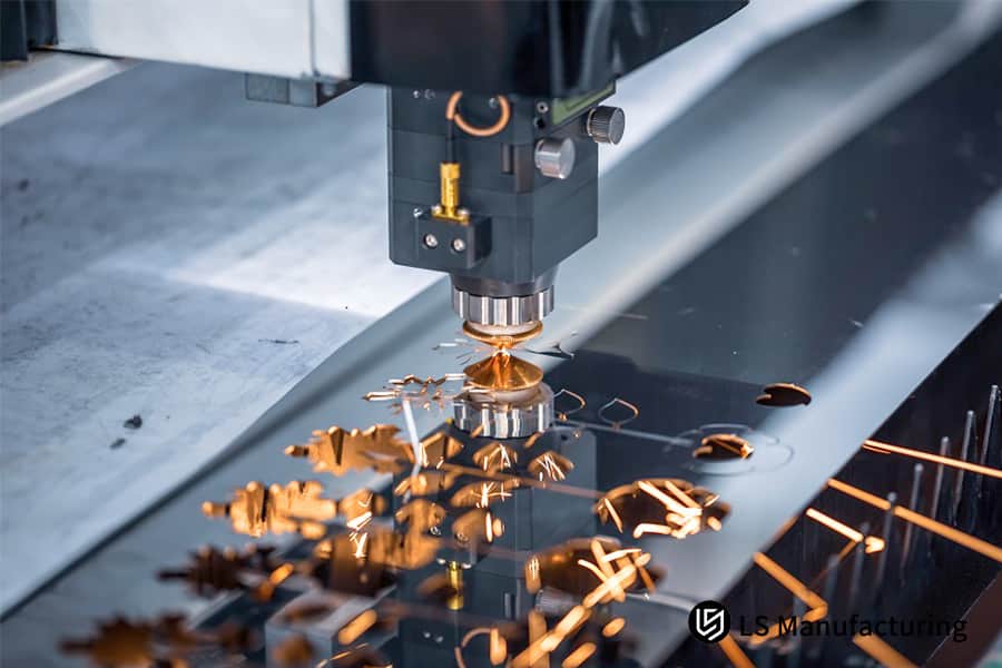
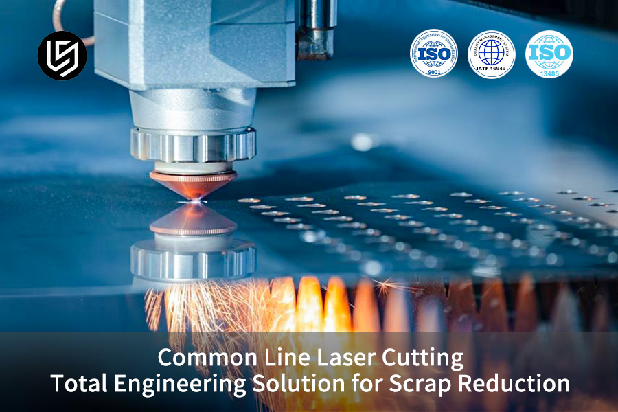
Figure 1: Precision fiber laser cutting head in action, slicing through sheet metal with glowing molten debris.
How Do Shared Tool Paths Increase Material Yield for a Better Scrap Reduction Solution?
At the heart of scrap reduction solution, one of the main logics is collinear laser cutting. This technique involves removing the isolation zones between the parts so that the adjacent parts can be cut along the same path. This way, the sheet metal utilization can be raised from the traditional 65%-72% to 85%-93%.
Principle of Geometric Efficiency Improvement through Collinear Nesting
Collinear cutting, from a geometry standpoint is equal to nesting optimization. Once zero-gap collinearity is achieved for L-shaped, rectangular, or irregular parts, the residual mesh waste can be removed completely. This is dependent on laser cutting layout optimization accuracy.
Utilization rate uplift effects for different part shapes are as follows:
| Part Type | Traditional Layout Utilization Rate | Collinear Layout Utilization Rate | Scrap Reduction Rate | Increase in Single-Board Part Count |
| Straight-edged Rectangular Parts | 72% | 93% | 75% | 29% |
| L-shaped Structural Parts | 68% | 89% | 65.6% | 30.9% |
| Regular Polygons | 67% | 87% | 60.6% | 29.9% |
| Irregularly Shaped Complementary Parts | 65% | 85% | 57.1% | 30.8% |
Cost Reduction Leverage Effect of Single-Board Output
For a regular metal sheet of 1500mm×3000mm, part output ratio can be increased by the use of collinear layout arrangement. The cost impact of the scrap reduction solution will be changed into the unit price of the purchase. A well-established laser cutting yield improvement method can greatly increase the cost reduction impact.
Cost reduction follows mainly three ways:
- By making more effective use of sheet metal, the user can decrease the cost of procurement per part.
- A drop in the number of perforations results in less material consumption and shorter processing time.
- Decrease in waste material may bring down costs of waste removal and recycling management.
Collinear cutting is like allowing adjacent cells to share an edge, saving space to accommodate more parts.You can download the "Collinear Cutting Cost Reduction White Paper" to obtain more industry waste data and material optimization case studies, and fully understand the value of implementing this process.
How Do We Adjust Kerf Compensation to Hold Tolerances in Your Laser Cutting Service?
For laser cutting service, collinear cutting demands accurate spot radius and path trajectory compensation which depend on the laser beam diameter being 0.15mm-0.25mm, otherwise, both collinear parts might concurrently present dimensional errors.
Offset Mathematical Model for Collinear Cutting
As the laser beam moves along the collinear path, the left and right parts overlap their respective outer and inner contours. To handle this, the microsecond level dynamic path compensation should be done with the aid of software like Sigmanest or Radan. The essence is the laser cutting offset calculation quite accurately.
Compensation is done using three rules:
- The part on the left side of the collinear path is offset by half the kerf width following its outer contour.
- The part on the right side of the collinear path is offset by half the kerf width as its inner contour.
- Non-collinear edges adhere to the conventional contour compensation regulations.
Multi-Parameter Linked Compensation Calibration Method
For machining precision parts of 0.05mm, calibration and compensation need to be integrated with parameters like lens focal length, auxiliary gas pressure, and nozzle height. This is a quality control process in the range of laser cutting service for high standards. Laser cut Kerf calibration is a standardized core activity to ensure tolerance stability.
The compensation parameters for different thicknesses of workpieces are as follows:
| Plate Thickness | Laser Power | Nitrogen Pressure | Knife Width | Single-Sided Compensation |
| 1.0mm | 3000W | 1.2MPa | 0.15mm | 0.075mm |
| 2.0mm | 6000W | 1.3MPa | 0.18mm | 0.09mm |
| 3.0mm | 10000W | 1.4MPa | 0.20mm | 0.10mm |
| 5.0mm | 15000W | 1.4MPa | 0.25mm | 0.125mm |
Knife compensation is like reserving the thickness of a pen when drawing a line, otherwise, the part dimensions will deviate. When parts are collinear, both sides will be affected.
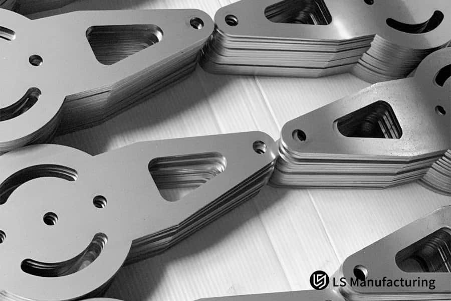
Figure 2: Neatly stacked piles of flat, laser-cut metal blanks and gaskets ready for the next manufacturing stage.
How Do Technicians Control Thermal Warp to Optimize Our Laser Cutting Engineering Solution?
Laser cutting engineering solution have to deal with one major challenge - controlling thermal deformation. Shared path machining can feature very long and continuous cutting lines, which cause high local heating at some points. To stop such thermal deformation the heat dissipation path has to be optimized and physical micro-connections have to be set up.
Thermal Expansion Behavior Analysis in Continuous Cutting
Continuous cutting of a long metal sheet in a straight line can cause residual stress release and thermal expansion in the metal - an old problem in laser cutting engineering solution.
At the point when the continuous cutting length in one direction exceeds 500mm, the sheet metal edge will start to show uplift or twisting at micron level, which can cause laser head collision. By our actual measurements, after a continuous cut of 500mm in 2mm aluminum alloy, the edge warping can be as much as 0.12mm, big enough to cause dimensional deviations.
LS Manufacturing Exclusive Thermal Deformation Control Solution
We come up with the solution for thermal deformation based on a three-fold engineering approach. With this, there is a unique LS Manufacturing-developed and optimized parameter: a 0.4mm micro-connection every 80mm. This laser cutting micro-tab design gives a good level of protection against aluminum alloy warpage:
- Segmented Stepped Asynchronous Cutting: Divides the long collinear sections into smaller intervals, This way preventing heat buildup from happening.
- Retained Micro-Connections: The sizes are locked in the range between 0.4mm and 0.6mm, as tensile stress balance is used to counter warpage.
- Optimized Torch Path Priority: Inner hole groups are processed first, then local collinear sections, and finally the outer setup.
Trying to control thermal deformation is similar to baking food in portions, but at the same time clamping the sheet metal to avoid warping due to heat. If your project faces the challenge of thermal deformation from thick collinear plates, you can schedule a one-on-one consultation with a process engineer for targeted path optimization suggestions.
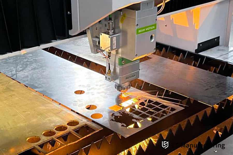
Figure 3: Large industrial laser cutting machine processing sheet metal with complex grid patterns and holes.
What Part Geometries Are Ideal for Reconfiguring a Total Laser Cutting Solution Service?
A total laser cutting solution service is an option that not all parts necessarily require. It is a perfect solution when the part profiles are rectilinear, regular polygons or irregularly shaped stamped/ machined parts of sheet metal type which can be nested complementarily.
Part characteristics suitable for collinear machining
From a DFM design viewpoint, the most suitable for collinear machining are parts with linear aligned edges, step joints, and complementary triangle shapes, which also act as the basics for the redesign of a total laser cutting solution service. Proper laser cutting geometry matching can much enhance the cost-saving advantages. Designers are able to make minute shape adjustments to the part so that it conforms to the collinear configuration, this way managing costs at the source.
Typical optimization directions are:
- Modify large rounded corners on non-assembly surfaces into straight edges with small rounded corners, while the basic collinearity is retained.
- Move locally protruding parts to the non-collinear side to avoid layout conflicts.
- Adopt a symmetrical design to make it easier for mirrored alignments and nesting.
Collinear processing forbidden features
Strictly forbidden from direct collinear processing are this features: parts with transition rounded corners R>3mm, molded parts with 3D reliefs or stretched flanges, and narrow, elongated areas with a wall thickness less than 1.5 times the plate thickness. This relates to basic laser cutting forming limitations. If collinearity is imposed forcibly, edge quality will deteriorate, parts may be deformed or become scrap.
Parts with straight edges can be easily joined through shared cutting lines, in contrast, parts with large rounded corners and a three-dimensional shape resemble curved building blocks that are hard to fit tightly.
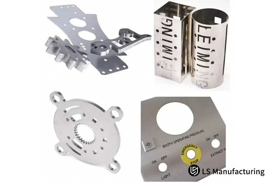
Figure 4: A collage showcasing various finished CNC and laser-cut sheet metal mechanical components and brackets.
How Should You Audit CAM Nesting Algorithms to Verify a Vendor's Scrap Reduction Solution?
One way of checking whether a supplier's scrap reduction solution works is by auditing their CAM layout algorithm and digital process management level. Closing the loop with high-end algorithms and automated equipment is the main support for collinear processing.
Typical Algorithm Issues of Low-End Manufacturers
Typically, low-budget processing plants are only equipped with free and open-source layout software without having highly skilled programmers. They can hardly manage complex processes like bridging collinearity and multi-part matrix collinearity. Their basic laser cutting nesting software can't support high-level collinearity requirements. These manufacturers usually have issues like repeated cutting, the absence of thermal deformation compensation, and exaggerated layout rates, with actual cost reductions being much less than those claimed.
Main Aspects of Procurement Audits
Procurement and technical personnel can screen high-quality factories from three dimensions to ensure that the supplier's scrap reduction solution is feasible for implementation. Thorough laser cutting algorithm verification is a core audit focus.
- Can the software automatically identify and delete duplicate lines via an algorithm that is foolproof to prevent secondary cutting damage of parts?
- Does the manufacturer have 10,000-watt ultra-high-power fiber laser equipment that is capable of supporting stable collinearity processing of thick plates?
- At the sample stage, does the manufacturer even offer DFM evaluation reports and nesting rate percentage screenshots?
Choosing a supplier is similar to choosing an artist, here the layout designer is the artist - good quality manufacturers will exploit sheet metal fully by using the professional software. In contrast, low-end manufacturers tend to waste more and make more errors.
How Do We Prevent Dimension Chain Amplification Across Shared Cut Lines in Thick Sheet Metal Design for Manufacturing?
In thick sheet metal design for manufacturing, the focus is shifted to the dimensional chain problem of collinear cutting. If residual stress in sheet metal is not properly balanced, continuous collinearity will cause stress release at the micron level plus displacement of materials. This problem is going to be solved by very accurate tolerance allocation coupled with a timing path cutting error accumulation.
Mechanism of Dimensional Chain Error Caused by Stress Release
When several parts share the same tangent, after the moment the previous part is cut, the sheet metal skeleton will experience a slight compression or rebound from the stress release. The instantaneous laser cutting stress release will local displacement. This displacement is usually in the 0.05mm-0.15mm range, and it won't processed nearby parts, which will lead to a cumulative dimensional chain deviation. If hole systems are being used, e.g. connectors of automotive battery packs, this effect can be quite pronounced.
LS Manufacturing Tolerance Locking Technology Solution
With core technology, within 0.03mm, the coaxiality and position of critical automotive grade holes are locked. This is also the main value of sheet metal design for manufacturing (SMT). Laser cutting tolerance gradual precompensation gets rid of any possible assembly interference risks:
- Utilizing a center-to-outer-radiating torch trajectoryto balance stress release and So to avoid unidirectional displacement accumulation.
- Presenting a two-level tolerance precompensation algorithmto pre-compensate the shift due to stress displacement during the programming stage.
- Performing a secondary precision cutting processcritical holes to completely eradicate the influence of cutting stress deformation.
How Do We Optimize Curved Edges and Micro-Tabs within a Laser Cutting Design Service?
A laser cutting design service could really unlock the cost reduction potential of collinear machining for curved or irregular contours through re-constructing CAM tangent trajectories and arranging process connections.
Mirror collinear nesting method for curved contours
Most engineers think only parts with straight edges can be collinearized. This is wrong and also a common laser cutting design service optimization blind spot. A very mature laser cutting arc nesting can totally exploit the cost saving potential of the parts irregular shapes. By reflecting the parts with arc or involute shapes that have the same radius in the opposite direction 180°, it is possible to get arc collinearity, because of this eliminating the gap waste.
Dynamic process control logic at inflection points
The core challenge of arc collinearity is the stability of the inflection point cutting. Stress rebound needs to be avoided through dynamic parameter adjustment. Dynamic laser cutting speed regulation is the core means of inflection point quality control.
The major control points include:
- At the inflection point reduce speed and simultaneously reduce laser power to get a uniform kerf.
- To ensure consistent quality, use constant linear speed mode for the arc segment.
- Make very small process supports at both ends of the arc collinearity to prevent from elastic rebound after cutting.
Arc collinearity is similar to the two halves of the circles placed back-to-back that share the same arc. By adjusting the turning speed and power, it is possible to get clean, precise, and material-saving cuts.
How Can Common Line Laser Cutting Reduce Total Piercing Counts across Your Complete Nesting Run?
The fundamental benefit of common line laser cutting is that it combines the cutting routes of neighboring components. It is possible to continuously cut several edges with a single piercing step. This way, the total piercing steps required for an entire plate can be cut down by more than 40%.
Analysis of Direct and Indirect Costs and Wear of Piercing Process
Piercing is singled out as the most time-consuming part of the machining process. Besides that piercing medium thickness plates involves a delay of 0.5-2 seconds for air blowing, it is the cause of the greatest consumables damage (nozzle and ceramic ring). It is well-known that piercing frequently leads to the intensification of the laser cutting nozzle wear and increases the chances of breakage of the hole and backflow contaminating the lens, which eventually leads to higher maintenance costs.
Here is a comparison of perforation efficiency at different board thicknesses:
| Board Thickness | Perforation Time | Number of Perforations per Board with Traditional Layout | Number of Perforations per Board with Collinear Layout | Perforation Time Reduction |
| 1.0mm | 0.5s | 120 times | 72 times | 40% |
| 2.0mm | 1.0s | 108 times | 56 times | 48% |
| 3.0mm | 1.5s | 96 times | 54 times | 43.8% |
| 5.0mm | 2.0s | 84 times | 48 times | 42.9% |
Efficiency Improvement Path for Collinear Cutting
LS Manufacturing Engineering team mixes the "continuous cutting" with the "collinear" techniques to realize "one-hole penetration, continuous wire feeding." Such coherent laser cut wire chain solution allows maximum efficient use.
Optimization results in threefold benefits:
- Lowered piercing frequency, single-piece processing cycle cut by 30%.
- Lesser degradation of vulnerable parts, like nozzles and ceramic rings, thereby increasing their lifecycle.
- Lower risk of hole bursts which, in turn, reduces lens contamination and equipment maintenance costs.
Case Study: How LS Manufacturing Saved a Tier-1 Automotive Supplier $14,500 via an EV Battery Component Laser Cutting Engineering Solution
This case study broke down how LS Manufacturing was able to come to the rescue of a Tier 1 automotive supplier who was facing issues with material waste reduction and precision dimensional tolerance bottlenecks. The way that they did it was by adding a collinear cutting solution into the manufacturing of high-voltage battery pack connector housings for new energy vehicles.
Customer Challenge
The problem that a global Tier 1 automotive supplier had was that they were required to personalize 80,000 aluminum alloy protective housings for EV lithium battery packs. They were made of 5052 aluminum alloy with the thickness of the wall being 2.0mm. Using the original single-piece independent layout method, there were always perforations and bursting of holes in the high-reflectivity aluminum alloy, which had caused edge burns.
High-frequency laser cutting hole burnout was the biggest reason of manufacturing defects, resulting in a sheet metal utilization rate of only 62.8%. Secondly, the parts warped and distorted due to heat accumulation, the tolerances of critical hole spacing were exceeded and the customer was at the risk of production line shutdowns and penalties.
LS Manufacturing Solution
Once our engineering team was done with the project, they started doing the sheet metal design for manufacturing review again.
- Our engineers redesigned the component of the collinear cutting solution from 2.0mm fillet edge to a straight-edge layout, and adapted the parts to the common line laser cutting method with a complementary matrix layout.
- A 20000W laser machine was used in the operation phase and 1.2MPa nitrogen purging to achieve the 0.15 mm kerf spot compensation at the 2.0 mm cutting workpiece edges.
- Based on the 400mm collinear edge length, the 0.4mm micro-connection was arranged in a spiral shape at the distance of 80mm to combined with the dynamic follow-up laser cutting height sensor (that made 500 measurements per second) to completely eliminate the warping problem of the high-reflectivity aluminum alloy.
Outcomes and Benefits
Due to the process optimization, the utilization rate of this material went up from 62.8% to 91.2%, the total number of perforations was reduced by 48%, and the processing time was cut by 35%. Laser gauge and CMM inspections confirmed that the hole spacing and the geometric tolerances of the 80,000 products were all consistently within 0.03mm, meaning they met the IATF 16949 100% automotive-grade assembly requirements.
The offer not only helped the client to avert the risk of production line downtime but also resulted in direct savings of $14,500 in raw material procurement. As a result, the client decided to outsource all custom parts for three vehicle models to LS Manufacturing.
If you also have similar precision sheet metal cost reduction needs, please send your project drawings and batch requirements. We will customize a dedicated common-line laser cutting solution for you and provide an accurate quote, quickly realizing the dual benefits of cost reduction and quality.

FAQs
Q1: Are common-line laser cutting techniques compatible with all types of automotive sheet metal materials?
It mainly applies to materials like stainless steel and carbon steel that have steady coefficients of thermal expansion to preserve cutting accuracy and surface quality. Long-distance common-line cutting on highly reflective and highly thermally conductive materials like brass and copper can cause arc interruption and heat buildup, Because of this pulse modulation processing solution is required from LS Manufacturing.
Q2: From what minimum size of a part can I have a laser cutting design with common line nesting?
If the length of the collinear straight edges of the parts exceeds 30mm, and the thickness of the plate is between 0.5mm and 12mm, LS Manufacturing will be able to use our proprietary optimized nesting algorithm to provide you with a flexible, low-loss, custom collinear processing solution that is capable of even material cost reduction.
Q3: How do you guarantee that the quality of surface finish is not sacrificed when it comes to shared paths with your end laser cutting solution?
Use of a 10,000 watt high power laser source, joining others like 1.4MPa constant nitrogen gas for uniform purging, while cutting two parts in one stroke the surface finish on both sides will be able to remain high-end industrial stably of the range Ra 3.2μm to 6.3μm for accuracy assembly needs.
Q4: Are the risks of laser head collisions heightened with the use of common line laser cutting when it comes to custom laser cutting services?
This is a process that often means collisions. Even so, LS Manufacturing still relies on the micro-connection fixing method in layout programming as one element with the combination of the intelligent jump and the real-time high-sensitivity elevation angle detection functions of the CNC system. Besides this, mass production verification demonstrates 0-collision, 24/7 unmanned production line operation.
Q5: Is it possible to combine parts from different orders into one common line nesting scheme to benefit from the scrap reduction solution maximally?
Definitely, you can combine/mix different orders, which is a main benefit of digital supply chain from LS Manufacturing. We are then able to use intelligent grouping and nesting diverse small-batch orders of the same material and thickness and help small-batch customized customers reduce their board amortization costs even by 20%.
Q6: How can the dimensional accuracy of two parts separated by a shared cut line be verified?
It is the 0.2mm kerf width that is taken into account for the actual dimensions of two parts during offline programming. Produced the first piece calibration makes use of a digital optical projection measuring instrument and CMM and ensures that the two part dimensions are symmetrical and consistent and tolerances comply with the standards.
Q7: Does your engineering solution include automatic double-line elimination in CAD drawings?
It is part of our system to perform automatic double-line elimination. The only thing you need to do is to send standard STEP or DXF format drawings, then LS Manufacturing's intelligent DFM software system and experienced process engineers will automatically eliminate the overlapping lines and output the best laser processing path, so you won't have to make secondary drawings.
Q8: What details do you need from me if I want to get a laser cutting engineering solution accurately priced?
Simply provide us with 2D/3D drawings (DXF, STEP, or DWG format) that include material specifications, thickness, and quantity to be processed, and our quotation team will provide you with a transparent quotation containing complete DFM optimization suggestions within 24 hours.
Summary
In summary, common line laser cutting is hardly just basic layout methods, it covers the entire laser cutting solution from sheet metal geometry, CNC machine tool dynamic thermodynamic compensation, to physical cutting of high-performance laser. The big production layout that simply increases the size of a single piece is being replaced gradually, as it makes high-value precision manufacturing projects less profitable. A manufacturing company can only succeed in global supply chain competition by trimming down the waste premiums through high-quality sheet metal design for manufacturing strategies integration with high-power flexible hardware and at the same time supplying 0.03mm automotive-grade tolerances.
Stop paying for the skeleton waste which results from the poor layout efficiency! In case your project is at the R&D and design stage for changing the automobile, medical, or industrial equipment, or the production costs have run away from you, LS Manufacturing's precision sheet metal and laser engineering teams will offer you the entire technical support. Via our free evaluation channel, you can upload your DXF/STEP format files and then our DFM consultants will offer a tailor-made cost reduction solution for the production line, separated from the transparent pricing, within 24 hours.
📞Tel: +86 185 6675 9667
📧Email: info@lsrpf.com
🌐Website: https://lsrpf.com/
Disclaimer
The contents of this page are for informational purposes only. LS Manufacturing services There are no representations or warranties, express or implied, as to the accuracy, completeness or validity of the information. It should not be inferred that a third-party supplier or manufacturer will provide performance parameters, geometric tolerances, specific design characteristics, material quality and type or workmanship through the LS Manufacturing network. It's the buyer's responsibility. Require parts quotation Identify specific requirements for these sections.Please contact us for more information.
LS Manufacturing Team
LS Manufacturing is an industry-leading company. Focus on custom manufacturing solutions. We have over 20 years of experience with over 5,000 customers, and we focus on high precision CNC machining, Sheet metal manufacturing, 3D printing, Injection molding. Metal stamping,and other one-stop manufacturing services.
Our factory is equipped with over 100 state-of-the-art 5-axis machining centers, ISO 9001:2015 certified. We provide fast, efficient and high-quality manufacturing solutions to customers in more than 150 countries around the world. Whether it is small volume production or large-scale customization, we can meet your needs with the fastest delivery within 24 hours. choose LS Manufacturing. This means selection efficiency, quality and professionalism.
To learn more, visit our website:www.lsrpf.com.